From STL to STEP: How Does Engineering Reverse Modeling Work?
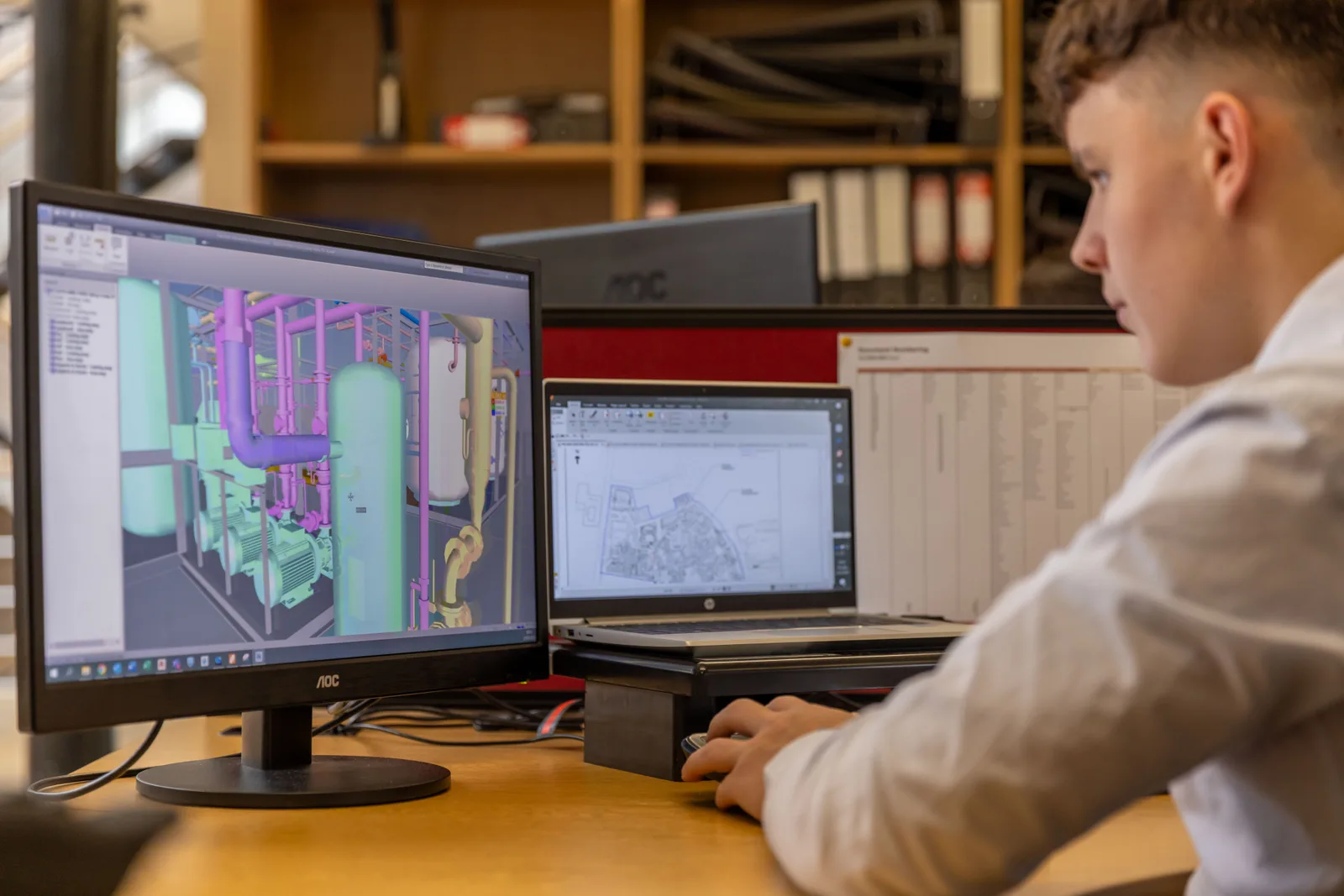
In digital manufacturing, it’s a common situation: a company has an STL file, but the next step in the process — CNC machining, CAM programming, or a design change — needs a STEP-format CAD model instead. This comes up especially often in industrial settings where the only file available for an existing part was made for 3D printing, while manufacturing calls for a parametric, editable model.
The question is more complex than “how do we convert STL to STEP?” STL and STEP are fundamentally different kinds of file formats. A simple file conversion usually isn’t enough — what’s needed is engineering reverse modeling (reverse engineering).
What is an STL file, and why isn’t it enough for industrial manufacturing?
STL (Standard Tessellation Language) is one of the best-known file formats in 3D printing. An STL model isn’t built from real geometric elements — it’s a mesh made of triangles. Put simply, it’s a digital “shell” around the part, not an engineering CAD model.
An STL file stores triangle coordinates, their orientation, and an approximation of the part’s outer surface. What it doesn’t store: dimensioned geometric features, the true diameter of holes, fillet parameters, design history, or editable CAD features.
That makes an STL file excellent for FDM or MSLA 3D printing, visual prototyping, and simple geometric checks — but it has limited use in industrial processes that require modifying the model or precise manufacturing. A CNC machinist usually can’t work from an STL file alone, since the CAM system needs exact geometric information to generate toolpaths.
STL, OBJ, and STEP — which file format is good for what?
STL is primarily used for additive manufacturing: it’s widely supported, produces small file sizes, and every major 3D printing software can handle it. Its downside: it’s not parametric, it’s hard to edit, and its accuracy depends on mesh density.
OBJ is also a mesh-based format, but it can store more information: textures, colors, material data, and multiple separate objects. It’s most common in visualization, 3D rendering, and scanning projects — but like STL, it isn’t a true CAD model, so on its own it doesn’t substitute for STEP in industrial manufacturing.
STEP (ISO 10303) is one of the most important formats in engineering design. A STEP file can carry real CAD information: surfaces, solid volumes, geometric relationships, and precise dimensions. That’s why it’s widely used in CNC machining, CAM programming, injection mold tooling, and industrial parts manufacturing — a STEP model can be imported directly into CAD systems like SolidWorks, CATIA, Siemens NX, or Fusion 360.
STEP is valuable in industry because it doesn’t just show what a part looks like — it describes its engineering geometry.
Why do clients want a STEP file made from an STL?
A common real-world situation: a company has an existing STL model — maybe it was used for an earlier 3D-printed prototype, received from a supplier, exported from an old system, or produced by a 3D scan. Later, the need arises for CNC manufacturing, a design change, series production, documentation, or a new revision — all of which require a STEP file or another CAD format.
At that point, it’s not a simple file conversion — it’s reverse modeling: an engineering process that creates a new CAD model from an existing physical or digital part. The classic design process runs from CAD model through manufacturing to physical part; reverse modeling runs in exactly the opposite direction — from the physical part or STL model, through geometric analysis, to an editable, dimensionable, manufacturable CAD model.
How does STL-to-STEP reverse modeling actually work?
The process has several steps.
Analyzing the STL geometry. First, we examine mesh quality, triangle count, surface defects, and the model’s accuracy. A poor-quality STL can have holes in the mesh, incorrect normals, too few geometric points, or a noisy surface — all of which make further processing harder.
Mesh processing. Next, the mesh is cleaned up: noise reduction, smoothing, defect repair, simplification. An overly detailed STL can contain millions of triangles, which significantly slows down CAD processing.
Creating the CAD geometry. This is the most important part of reverse modeling. The engineer determines the position of planes, hole axes, arcs, fillets, and standard geometric features, then builds the real CAD model from them. A hole in an STL doesn’t exist as a “hole” — it’s just a circular opening in the triangle mesh. In the CAD model, though, its diameter, depth, tolerance, and position can all be properly defined. That’s what makes it suitable for industrial manufacturing.
Can STL-to-OBJ or STL-to-STEP conversion be automated?
STL-to-OBJ conversion is relatively simple in some cases, since both formats are mesh-based — a converter can save the same triangle mesh into an OBJ file. This isn’t a true reconstruction, though: the geometry stays mesh-based, it won’t become a parametric CAD model, and it won’t be STEP-compatible.
Automatic STL-to-STEP conversion can work for certain simple models — if an STL has few triangles, contains simple planar surfaces, and is built from regular geometric features (a box-shaped part, a cylinder, a simple cover), software may be able to generate an approximate CAD geometry. For complex industrial parts, though, automatic conversion often produces flawed results: too many surfaces, imprecise edges, incorrect holes, and a CAD model that’s hard to work with. That’s why manual engineering reverse modeling remains the standard in professional industrial applications.
What role does 3D scanning play in reverse modeling?
If there’s no STL file, the starting point is often the physical part itself — the process then runs from the part through 3D scanning and a point cloud to a mesh, and finally to a CAD model. Not every part needs scanning, though: in an earlier article, we go into detail on when traditional measurement is enough, and when scanning genuinely earns its place in the process.
Modern 3D scanning technologies make it possible to digitize existing machine parts, remanufacture worn components, and document old designs — especially useful when there’s no manufacturing documentation, no CAD data, and the original manufacturer is no longer available. That’s exactly what happened when remanufacturing a discontinued VW Golf 2 throttle lever: with no factory part or documentation to go on, 3D scanning and reverse modeling produced an editable CAD model, and from it, the finished replacement part.
How does this connect to industrial 3D printing and CNC machining?
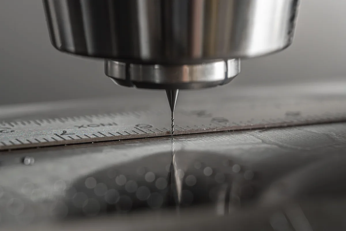
In modern manufacturing, 3D printing is no longer just for prototypes — industrial FDM and MSLA technologies, as we cover in our article on the basics of 3D printing, are also well suited to functional prototypes, small production runs, custom parts, and manufacturing aids. A typical workflow: digitize the existing part, reverse-model it in a CAD system, optimize it for manufacturing, produce a 3D-printed prototype, then set up the final production process — whether that’s 3D printing or CNC machining.
The same STEP model underpins both manufacturing paths. That can significantly cut development time and traditional manufacturing costs, since the engineering work doesn’t have to be redone at every manufacturing step.
When is STL-to-STEP reverse modeling worth choosing?
This approach is especially recommended when there’s no original CAD model, when CNC manufacturing needs precise geometric data, when an existing part needs modification, when series production is starting, or when an old part needs to be reproduced.
Summary
Reverse modeling isn’t a simple file conversion — it’s an engineering reconstruction that enables the next step in digital manufacturing. An STL file serves 3D printing well, but on its own it isn’t enough for the editable geometry that CNC manufacturing, modification, or series production require.
Two practical takeaways: first, don’t rely on automatic STL-to-STEP conversion for complex industrial parts — the flawed holes and imprecise edges it produces often cost more to fix than a careful engineering reverse modeling job would have cost in the first place. Second, the output of reverse modeling — an editable STEP file — can serve as the basis for both 3D printing and CNC machining, so the engineering work isn’t locked into a single manufacturing technology.
If you need a manufacturing-ready, editable CAD model from an existing STL file or physical part, request a quote for our parts manufacturing service — we work from the reverse-modeled STEP file with both industrial 3D printing and CNC machining.
Related Articles

Planning a Similar Project?
Send us your model or drawing — free consultation, with personalized quotes within 24 hours.