Broken Part? Is 3D Scanning Really Necessary for Reverse Engineering?
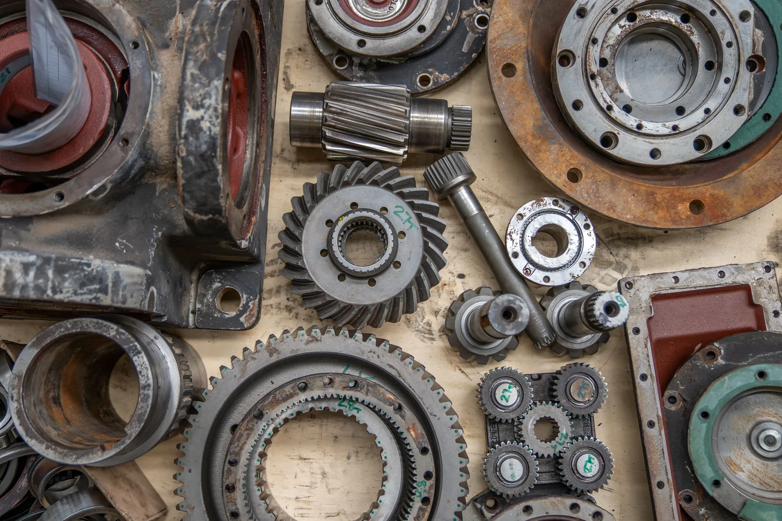
In industrial maintenance, repair, and custom parts manufacturing, it’s common to need a replacement for an old, discontinued, or simply broken part. Many people automatically assume the solution is 3D scanning, since it seems like the most modern technology available — but the reality is far more nuanced.
From an engineering perspective, 3D scanning isn’t always the most economical or best solution. Many parts can be remodeled faster, more accurately, and more cost-effectively using traditional measurement methods. In a professional reverse engineering project, we always check first whether scanning is genuinely necessary, or whether classic engineering measurement is enough.
The most common misconception: every part needs scanning
Interest in 3D scanning has grown significantly in recent years, and as a result, many companies assume that the first step in replacing any broken part is a scan. In reality, this isn’t justified for most of our inquiries: many of the parts we receive are turned components, sheet-metal parts, mechanical spacers, simple covers, standard machine elements, or well-defined mechanical parts. Their geometric features can easily be measured with traditional tools — a full scanning process would just be an unnecessary added cost.
When is traditional measurement enough?
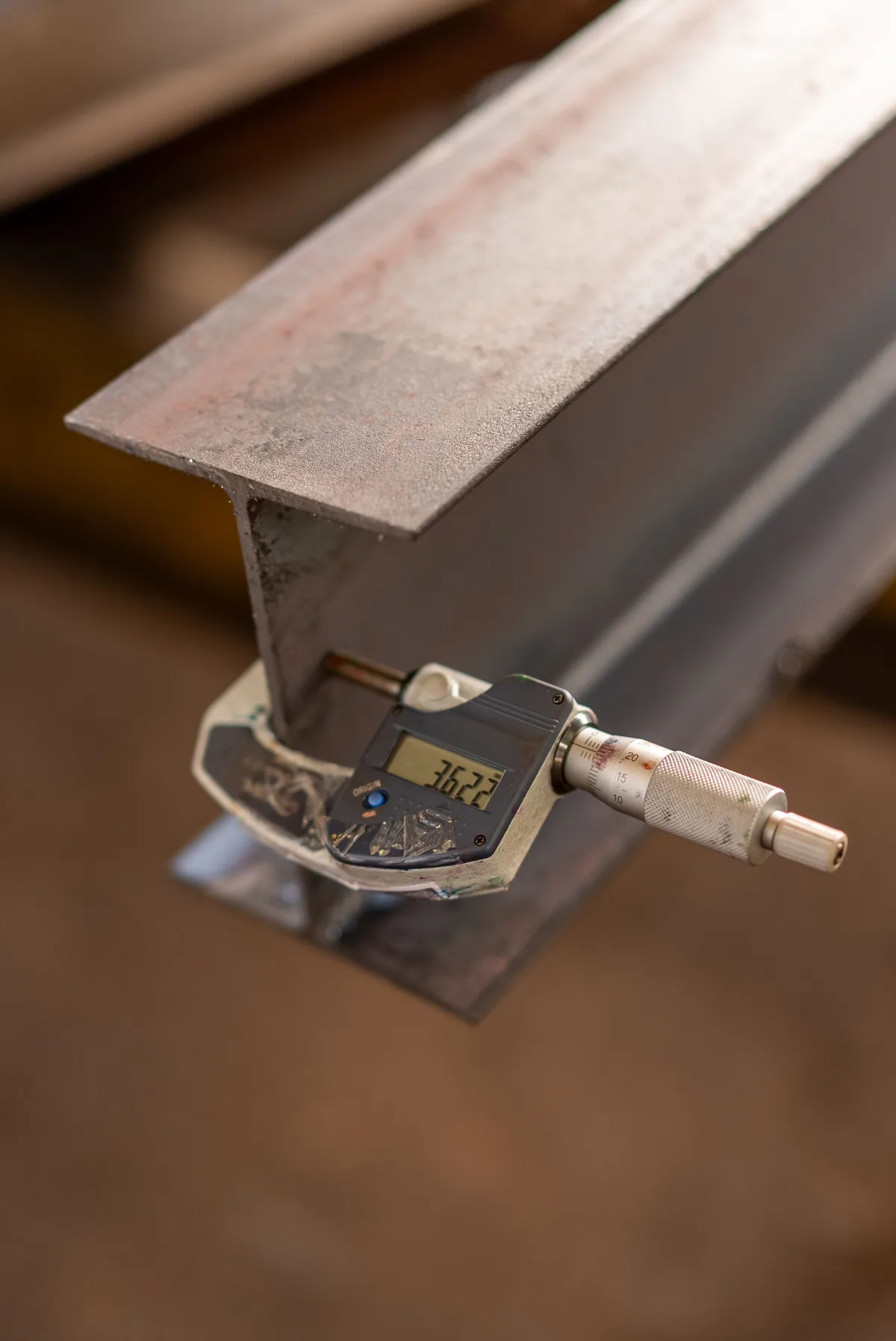
For an experienced mechanical engineer, the geometry of many parts can be determined in just a few minutes. A digital caliper, micrometer, depth gauge, bore gauge, thread gauge, protractor, or dial indicator is often all it takes. Once the dimensions are captured, a parametric CAD model is created that’s ready for 3D printing, CNC machining, injection mold design, and manufacturing documentation — this method is often faster and cheaper than 3D scanning itself.
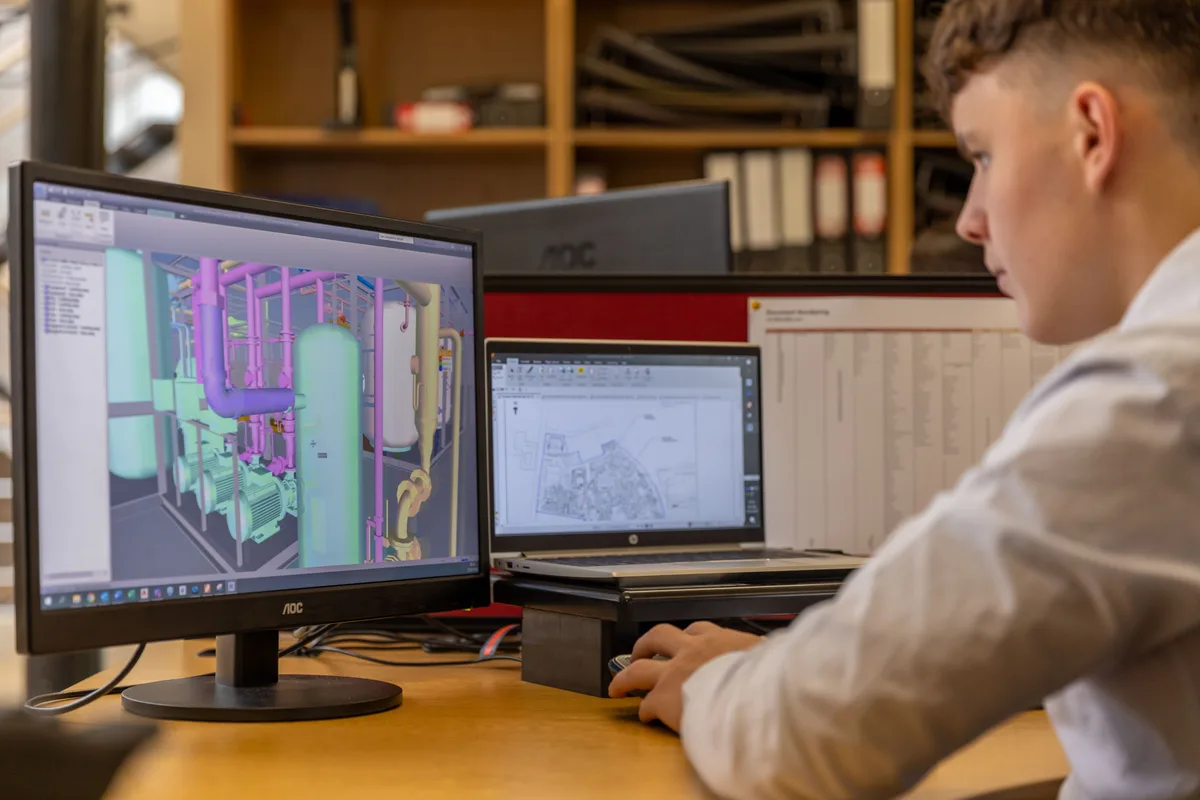
A parametric CAD model is more valuable in the long run than a raw scan result. The immediate output of scanning isn’t an editable CAD model — it’s a point cloud, mesh, or STL file. These are excellent for 3D printing, but have limited use for later modifications. A model built from traditional measurements, on the other hand, is fully parametric: hole placement, wall thickness, ribbing, fits, and dimensions can all be easily adjusted later — which matters a great deal in industrial parts manufacturing.
When is 3D scanning genuinely justified?
There are, of course, plenty of cases where 3D scanning isn’t just useful but practically essential.
Amorphous and organic surfaces. Hand-formed or cast parts — castings, ergonomic grips, plastic housings, vehicle interior components, design products, sculptures, or prototypes — often have no regular geometric features, with surfaces made of continuously changing curves. Measuring these by hand would take enormous amounts of time, while 3D scanning delivers a far more accurate result.
Heavily worn parts. When a part is partially worn, the original geometry can be reconstructed by comparing multiple samples, partial scanning, and engineering reconstruction.
Large parts. For machine frames, tooling, welded structures, vehicle components, or production-line elements, an industrial 3D scan can significantly shorten a project compared to manually capturing hundreds of measurement points.
How does a professional 3D scan actually work?
Many people imagine the process as simply pointing a scanner at a part and getting a finished model within seconds — the reality is considerably more involved. The part is first cleaned, degreased, and dedusted, since a contaminated surface can significantly reduce scanner accuracy. Many industrial parts are shiny, chrome-plated, polished, or translucent, which laser scanners struggle to detect — so a special, evaporating 3D scanning spray is applied to the surface, which disappears without a trace within a few hours.
On large or uniform surfaces, the scanner can’t always determine its own position, so reference markers are placed on the part, improving measurement accuracy and reducing alignment error. Hundreds of shots are taken from different angles and positions on a complex part, and software stitches the resulting point clouds together, followed by noise reduction, error correction, hole filling, and mesh optimization — this step often takes longer than the measurement itself. The finished model can be exported as STL, OBJ, PLY, STEP, or IGES, depending on its intended use.
What happens next? Reverse engineering
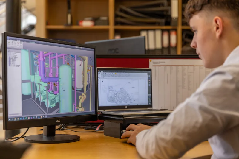
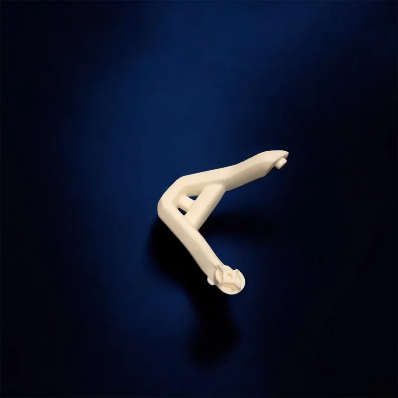
Many people assume a part is ready to manufacture right after 3D scanning — that’s only partly true. If modification or a precise CAD model is needed, that’s when reverse engineering begins: based on the point cloud or mesh, a fully parametric CAD model is created, ready for modification, optimization, sizing, and manufacturing documentation. This step requires engineering experience — the goal isn’t simply to copy the surface, but to understand how the part functions and produce a CAD model that remains usable in the long run, as we demonstrated when remanufacturing a discontinued VW Golf 2 throttle lever.
The role of 3D printing in replacement parts
Once the CAD model is ready, several manufacturing technologies can be used. For small quantities, 3D printing is often the most economical solution: depending on the application, FDM technology with engineering plastics or MSLA technology for high-detail parts can be used — as we cover in detail in our article on how FDM and MSLA technology works. If quantities increase later, the same CAD model can also be used for CNC machining or injection mold design.
Summary
Every project deserves the same mindset: the goal isn’t to apply 3D scanning at all costs, but to choose the most economical engineering solution possible. In many cases, a few precise measurements are enough, the CAD model is finished faster, and the project costs less. In other cases, 3D scanning delivers significant time savings and greater accuracy.
Choosing the right technology is always an engineering decision based on the part’s geometry, condition, and end use — never an automatic process. If you need to replace a broken, worn, or discontinued part, request a quote for our parts manufacturing service — our engineers will always assess whether traditional remeasurement is sufficient, or whether full 3D scanning and reverse engineering is genuinely warranted.
Related Articles
Planning a Similar Project?
Send us your model or drawing — free consultation, with personalized quotes within 24 hours.